Electronic devices will generate a certain amount of heat when working, so that the internal temperature of the device rises rapidly, if the heat is not distributed in a timely manner, continued heating, the device will fail due to overheating, the reliability of electronic equipment performance will be reduced. Therefore, a good thermal treatment of PCB circuit boards is very important.
.jpg)
This blog will discuss the PCB circuit board heat dissipation techniques to exchange ~
1. PCB heat dissipation itself
PCB heat dissipation is a simple, practical, low-cost way to dissipate heat. The current PCB circuit board board is mainly: copper / epoxy glass cloth substrate or phenolic resin glass cloth substrate, although these substrates have excellent electrical properties and processing performance, but poor heat dissipation can hardly be expected to conduct heat by the PCB itself resin. Therefore, it needs to be designed to dissipate heat from the surface of the component to the surrounding air.
So how to do it? The best way to improve the direct contact with the heat-generating components of the PCB's own heat dissipation capacity, through the PCB board conduction out or emitted. For example, add heat dissipation copper foil and the use of large-area power ground copper foil, heating over the hole, in the back of the IC chip exposed copper, reduce the thermal resistance between the copper skin and the air and other ways.
2. Optimize the layout of components
Devices on a PCB printed board should be arranged as far as possible according to their heat generation and heat dissipation degree of partitioning, heat generation or heat-resistant devices (such as small signal transistors, small-scale integrated circuits, electrolytic capacitors, etc.) placed in the uppermost stream of cooling airflow (entrance), heat generation or heat-resistant devices (such as power transistors, large-scale integrated circuits, etc.) placed in the most downstream of the cooling airflow. Avoid the concentration of hot spots on the PCB, as far as possible, the power is evenly distributed on the PCB board to maintain uniform and consistent temperature performance of the PCB surface.
The heat dissipation of the printed circuit board within the device mainly relies on air flow, so the air flow path should be studied during design and the device or printed circuit board should be reasonably configured.
In the horizontal direction, high-power devices are arranged as close as possible to the edge of the printed board in order to shorten the heat transfer path; in the vertical direction, high-power devices are arranged as close as possible to the top of the printed board in order to reduce the impact of these devices on the temperature of other devices when working, as follows.
.jpg)
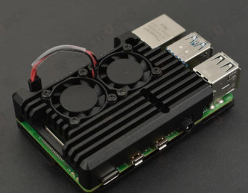
3. Add heat sink
If the PCB itself is not good for heat dissipation, you can add a heat sink or heat pipe on the heat-generating devices, when the temperature can not be lowered, you can use a heat sink with a fan to enhance the effect of heat dissipation, the heat sink cover the whole buckle on the component surface, and each component contact and heat dissipation, as follows.
If available, the thermal performance analysis of the printed circuit is necessary, such as the thermal performance index analysis software module now added to some professional PCB design software, it can help designers optimize the circuit design.


-20x20-20x20.png)

