1. UART
UART is called Universal Asynchronous Receiver-Transmitter, which is usually used for a communication connection between chips and external devices. When we say serial port in embedded, it usually means UART port. Embedded systems often use the UART port to connect to the COM port of the host PC (or to connect to the USB port of the host after converting the UART to USB) for debugging, so that the printf function in the embedded system can be redirected to print to the display of the host.
The data transmission format of UART is as follows.
.jpg)
During the transmission process, the UART sender sends out the byte data bit by bit in serial, and the receiver receives the data bit by bit and then reorganizes it into byte data. the UART transmission rate is measured by Baud Rate (Baud Rate).
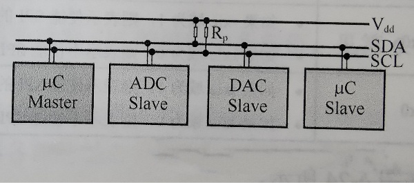
2. I2C
I2C is a simple, bi-directional two-wire synchronous serial bus developed by Philips, which requires only two bus lines: a serial data line SDA and a serial clock line SCL, and supports bi-directional communication. The main features of I2C are as follows.
Support for writing data to or reading data from an external I2C slave device as an I2C master device.
Support for generating transmit or receive terminals.
Support for configuring the frequency of the serial clock line SCL via registers.
Each device connected to the bus can be identified using a unique address.
Actual multi-host bus with conflict detection and arbitration to prevent data corruption when two or more hosts initiate the data transfer at the same time.
3. I2S
I2S, known as Inter-IC Sound, is a bus standard developed by Philips for audio data transmission between digital audio devices, which is dedicated to data transmission between audio devices and is widely used in various multimedia systems. In this protocol, data signals and clock signals are transmitted along separate wires, thus avoiding signal distortion caused by time differences.
4. SPI
SPI works in a master-slave mode, usually with one master device and one or more slave devices, and requires at least four wires (for full-duplex method) or three wires (for half-duplex mode), namely SDI (data input), SDO (data output), SCK (clock), and CS (chip select). The GPIOs are the GPIOs of the GPIOs, and the CS (chip select).
5. GPIO
GPIO is called General Purpose Input/Output, general purpose input/output interface. Each I/O pin can be directly controlled by software programmable configurable registers (software control mode) or directly controlled by hardware interface signals (IOF mode), and can be used as CLK Generator, Chip Select, etc.
6. PWM
PWM, known as Pulse-Width Modulation, is a common module in MCU. PWM uses the digital output of MCU to control analog circuits and is widely used in many fields of measurement, communication, power control, and switching.
7. WDT
WDT is a timer circuit that has one input, commonly known as "watchdog", and one output, which is connected to the MCU's global reset. During normal operation, the MCU will "feed" the WDT at regular intervals, and if it does not "feed" for more than a specified period of time (such as when the program is running away), the WDT will trigger a timing timeout, after which a reset signal will be sent. After the timeout, a reset signal will be sent to the MCU to reset the MCU globally and prevent the MCU from crashing. In short, the role of the watchdog is to prevent the program from dead loops or program runaway and other error situations.
8. RTC
RTC, known as Real-Time Clock, is a common module in MCU, mostly using a crystal oscillator with high precision as the clock source.RTC is usually in the power-on domain in the MCU system, running at a fixed low-speed clock, so it can provide absolutely accurate time reference, so it is called a real-time clock.
9. PMU
PMU is a commonly used module in MCU. PMU is usually in the power-on domain in the MCU system and controls the power on/off of other parts of the MCU SoC to achieve higher power conversion efficiency and lower power consumption.


-20x20-20x20.png)

