In PCBA processing, SMD components and DIP components are used.
So, what is the difference between SMD components and plug-in components?
l The advantages of both
Advantages of SMD components
1. reduce the size of the product: SMD components are only about 1/10 of the volume of traditional cartridge components; general SMT processing, electronic products to reduce the volume of 40% to 60%.
2. improve production efficiency, reduce costs: SMT chip processing is easy to achieve automation, improve production efficiency, saving materials, energy, equipment, manpower, time, etc., reduce costs up to 30% ~ 50%. Easier to weld than plug-in components.
3. lightweight: the weight of SMD components is only 10% of the traditional plug-in components; general use of SMT after the weight of the product to reduce 60% ~ 80%.
4. high reliability, strong anti-vibration ability.
5. high-frequency characteristics, reduce electromagnetic and radio frequency interference. Because the SMD components without leads, reducing the stray electric field and magnetic field, which is particularly effective in high-frequency analog circuits and high-speed digital circuits.
6. low defect rate of solder joints.
Advantages of DIP components
1. are power-type devices, high requirements for heat dissipation, its performance is much higher than the chip components, more stable and durable to maintain the performance of the product.
2. low failure rate, easy to inspect, can be intuitive feedback out of bad, without the use of special equipment instruments.
l The different soldering methods
SMD components soldering method
Components will be placed on the pad, in the component surface and pad contact smear tuned SMD solder paste, and then 20W internal heating type soldering iron to the pad and SMD components connected to heating (temperature should be in 220 ~ 230 ℃), see the melting solder can be taken away from the soldering iron, to be solder solidification after the welding is complete. After welding can be clamped with tweezers to see whether the welded SMD components are loose, no loose that is to say good welding, such as loose should be re-wiped point solder paste re-welding according to the above method.
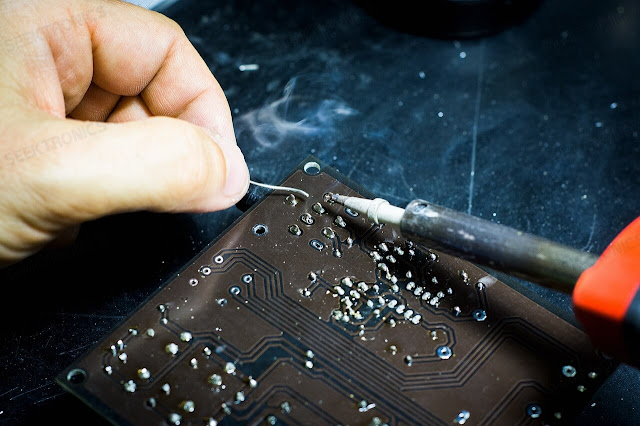
DIP components soldering method
When soldering all pins, the solder should be added to the tip of the soldering iron and all pins should be coated with flux to keep the pins moist. Touch the end of each pin of the chip with the tip of the soldering iron until the solder flows into the pin. After soldering all the pins, wet the pins with flux to clean the solder to eliminate any shorts and laps. Finally, check for dummy solder with tweezers and when finished, remove the flux from the board by carefully wiping a stiff brush soaked in alcohol along with the pins until the flux is gone.
The above is Seektronics for you to explain the SMT processing SMD components and cartridge components difference, we hope it will help you.


-20x20-20x20.png)

