l Polarity definition
Polarity means that the positive and negative poles or the first pin of the component are in the same direction with the positive and negative poles or the first pin on the PCB(printed circuit board). If the direction of the component does not match with that on the PCB, it is called reverse defect.
l polarity identification method
1. Resistor without polarity

2. Capacitor
2.1 Ceramic capacitors without polarity

2.2 Tantalum capacitors have polarity
PCB board and components positive marking: 1) colour band marking; 2) "+" sign marking; 3) angled marking.

2.3 Aluminium electrolytic capacitors have polarity
Part marking: colour band for negative; PCB board marking: colour band or "+" sign for positive.

3. Inductor
3.1 Chip Coils
Chip inductors and other two solder end packages have no polarity requirements.

3.2 Multi-pin inductors
Multi-pin inductors have polarity requirements. Part markings: dot/"1" for polarity point; PCB markings: dot/circle/"*" for polarity point.

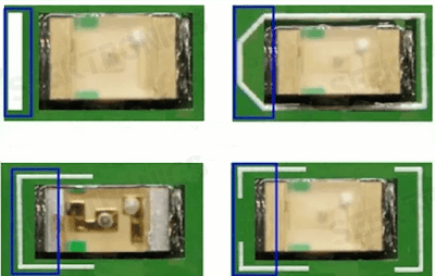
4.1 SMT surface-mounted LEDs
Surface-mounted LEDs have polarity.
Parts negative labeling: green for the negative pole;
PCB negative labeling: 1) vertical bar on behalf of; 2) ribbon on behalf of; 3) silkscreen sharp corner on behalf of; 4) silkscreen "匚" box on behalf of.
5. Diode
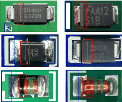
5.1 SMT surface-mounted two-terminal diodes
Surface-mounted two-terminal diodes have polarity.
Negative part marking: 1) ribbon, 2) notch, 3) colour marking (glass body).
PCB negative marking: 1) vertical bar marking, 2) ribbon marking, 3) silk-screened sharp corner marking, 4) "匚" box marking
6. Integrated Circuit
6.1 SOIC type packages
These packages are polarised. The polarity is indicated by 1) a ribbon, 2) a symbol, 3)concave point, groove, 4) beveled edge

6.2 SOP or QFP type packages
These types of packages have polarities. The polarity is marked by 1) concave points/grooves 2) the (size/shape) of one of the dots being different from the other two/three.

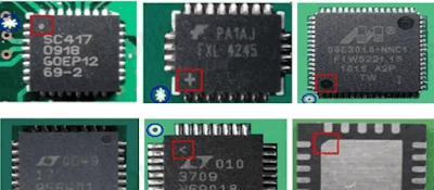
6.3 QFN type packages
This type of package has polarity. The polarity is marked by 1) a dot that differs from the other two (size/shape), 2) a bevelled edge, and 3) a symbol (horizontal bar/"+" sign/dot).
7. Ball Grid Array
Part polarity: dots/notches/rounds/circles.
PCB board polarity: circle/dot/letter "1 or A"/beveled mark.
The part polarity points correspond to the polarity points on the PCB.


-20x20-20x20.png)

