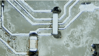
Two points in the design of the circuit board can not be connected with the printed circuit, often in the front with cross line connection, which is often seen in the ordinary board, in order to make the automatic chip machine and automatic insert machine work normally, with zero resistance instead of cross line.

0 Ohm resistor for span lines on single sided PCBs
A summary of the role of the 0 ohm resistor can include the following:
l No function in the circuit, just on the PCB for debugging convenience or compatible design, etc.
l Can be used as a jumper to avoid high frequency interference (becoming an antenna) caused by using jumpers.
l When the parameters of the matching circuit are uncertain, 0 ohm is used to replace them. In the actual debugging, the parameters are determined and then the specific numerical components are used to replace them.
l 0 Ohm resistor is actually a resistor with a very small resistance value, when you want to measure the current consumption of a certain part of the circuit, connect the 0 Ohm resistor and connect the ammeter, so that it is convenient to measure the current consumption and can be used to measure large currents.
0 Ohm resistor for span lines on single sided PCBs
When wiring, you can also add a 0 ohm resistor if you just can't lay it over.
Acts as an inductor or capacitor under high frequency signals. (Related to external circuit characteristics) Inductors are used, mainly to solve EMC problems. Such as ground to ground, between power supply and IC Pin.
Single-point grounding (refers to the protection grounding, working grounding and DC grounding are separated from each other on the equipment and become independent systems respectively.)
Do circuit protection, acting as a low-cost fuse (circled USB circuit with 0 ohm 0603 resistor acting as USB overcurrent protection) Due to the large fusing current of the PCB alignment, if a short circuit overcurrent and other faults occur, it is difficult to fuse, which may lead to greater accidents.
As the 0-ohm resistor current withstanding capacity is relatively weak (in fact, 0-ohm resistor also has a certain resistance, just very small), overcurrent will first 0-ohm resistor fuse, thus breaking the circuit, preventing a larger accident. Sometimes small resistors with a resistance of zero or a few ohms are also used as fuses. However, this is not recommended, but some manufacturers use this to save cost.
In mixed circuits such as digital and analogue, it is often required that the two grounds are separate and connected at a single point. Instead of connecting the two grounds directly together, we can use a 0 ohm resistor to connect the two grounds. The advantage of this is that the ground is split into two networks, which makes it much easier to handle when laying copper over large areas, etc. As a side note, such occasions are sometimes connected with inductors or magnetic beads etc.
Configure the circuit so that jumpers and dip switches do not normally appear on the product. Sometimes users will mess with the settings, which can easily lead to misunderstandings. To reduce maintenance costs, 0 ohm resistors should be soldered to the board instead of jumpers etc.
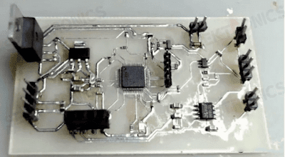
Single-sided PCBs
How much current can a zero ohm resistor hold? When designing a circuit that often uses zero-ohm capacitors, the resistor rating is generally chosen based on the line current, so how much of the 0-ohm is generally chosen to fit.
The actual resistance of a normal 0 ohm resistor is about 50 mΩ +-5% deviation. So based on the power rating, you can figure out its current rating.
l 0402 1/16W: 1/16=I*I*0.05 i.e. I=1.118A;
l 0603 1/8W: 1/8=I*I*0.05 i.e. I=1.58A;
l 0805 1/4W: 1/4=I*I*0.05 i.e. I=2.236A;
The exact amount of current that can be passed through a 0 ohm resistor in each package is determined by the heat dissipation of the resistor on the PCB.
The following tests show the relationship between the current passed and the voltage across the resistor in the 0603, 0805 and 1206 packages respectively. It can be seen that for all three packages the voltage starts to rise rapidly after the current actually exceeds 6A.
Testing the maximum current flow through a 0 ohm resistor
This indicates that the temperature of the resistors also increased dramatically, resulting in a substantial increase in power consumption as well. 0603 resistors burned out when the current increased to 11.5A, 0805 resistors burned out when the current increased to 12A, and 1206 resistors did not burn out at 12A.

0603 package 0 ohm resistor curve between current and voltage
0805 package 0 ohm resistor curve between current and voltage
1206 package 0 mm resistor curve between current and voltage


-20x20-20x20.png)

